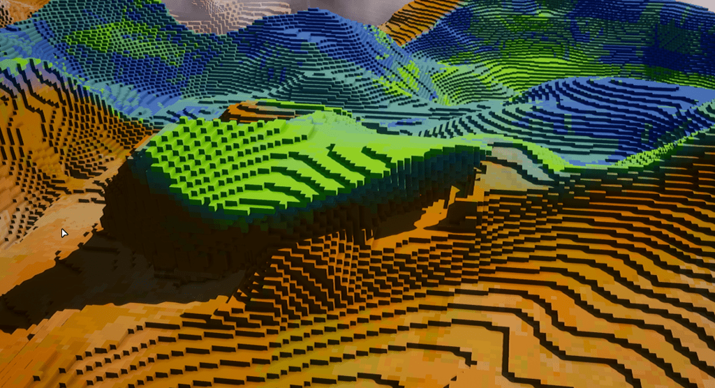
Chunks are the main subdivision unit of our map. They represent a 3d space containing blocks. Each chunk holds the data relative to the blocks it contains. Generating the actual data for these blocks (what kind of block they are, whether they’re solid or empty, etc) will be the subject of a future article.
For now, we’re going to cover how to mesh these chunks so the player can actually see the blocks.
Many articles have been written on the subject, by people way smarter than I am, so I will be mainly focusing on one aspect that is slightly less common (as far as I know) regarding this meshing technique.
One popular one, I think, is this: https://0fps.net/2012/06/30/meshing-in-a-minecraft-game/
You should familiarize yourself with the above, or watch the following video:
Only mesh what you can see
The first thing to understand is that, as we deal with very large maps and potentially millions of blocks to display on screen at any given time, we need to think about speed and optimisation.
It would be tempting to just loop through all the blocks and generate full cubes at their location. You’ll soon realize it isn’t a realistic approach, as the sheer number of blocks will kill any modern machine, provided you want maps that are bigger than a small kids sandbox in a playground. You might give a brief go at instancing cubes, but you will inevitably reach the same conclusion: meshing or instancing this ridiculous amount of blocks is just a non-starter.
That’s it, we can pack it guys, and abandon our project. Time to make a Tetris clone and, if we’re daring, maybe we will add some particle effects.
Just kidding. We can’t mesh all those blocks, no, but do we need to?
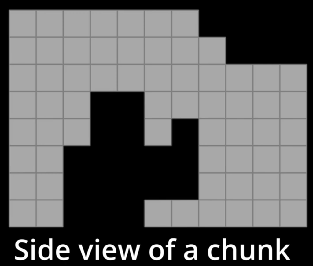
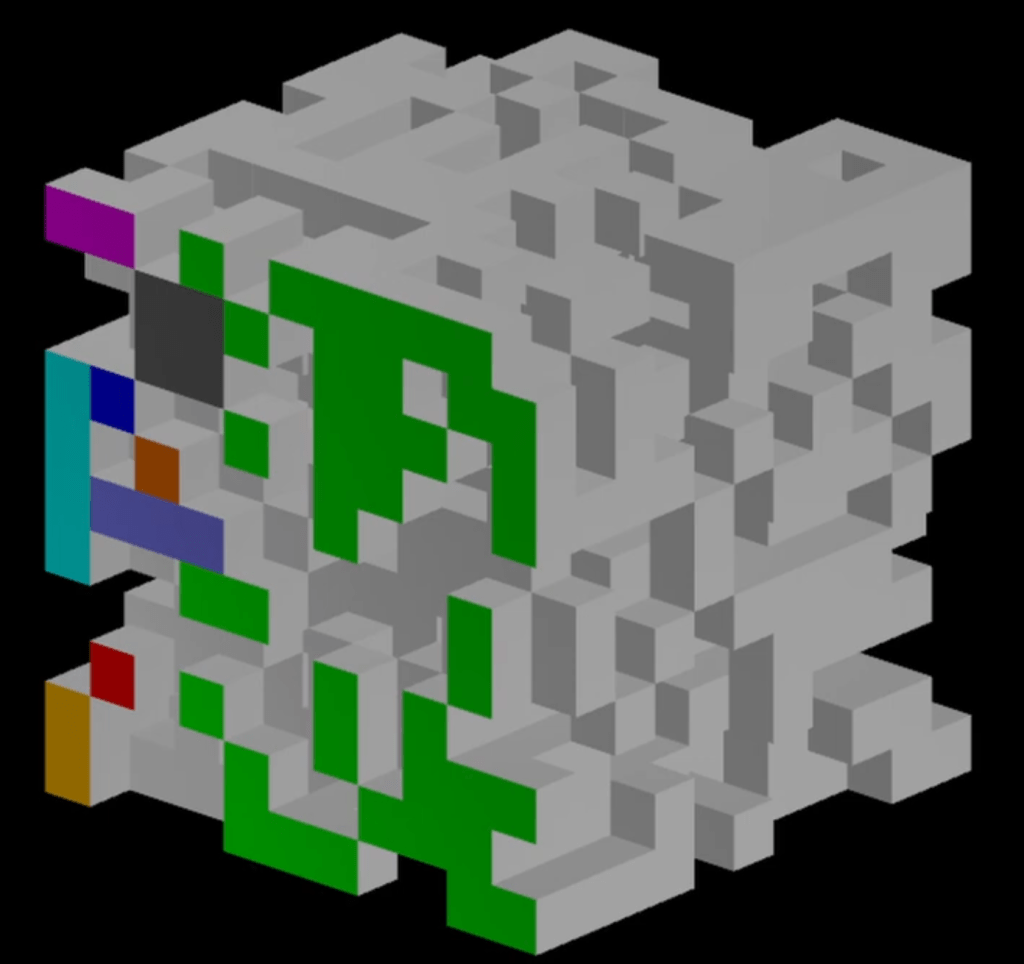
Imagining our game is a 2d sidescroller, here are the blocks that the player can actually see in game, from the image above:
All darkened blocks can never be seen, because the lighter blocks completely hide them. They could eventually get revealed, if one of the adjacent blocks is destroyed, for example, but for now they’re not.
This can already drastically cut the number of blocks we have to deal with. But that’s not all. We only care about what is visible, right?

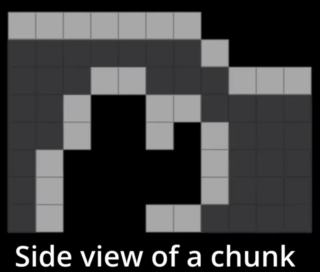
The green lines represent the faces that are actually visible. We’re not meshing blocks, we’re only meshing visible faces.
Detecting which face is visible
From the above, you might already have realized the following: visible faces are faces of solid blocks that are directly adjacent to an empty block.
Depending on the needs of your projects and your expectations, you might be okay just looping through all blocks, checking the 6 adjacent blocks one by one and adding quad meshes for each empty adjacent block you find.
However, there is a way of holding the data in our chunks that can greatly improve this step. As we discovered earlier, we only care about one simple binary state: whether a block is solid or empty. At this point, we don’t care about the type of block yet.
In my project, the chunk data is arranged in two elements: the block types (not discussed in this article) and the presence mask.
This presence mask can be thought of as a boolean array: each block in the 3d chunk is represented by a 0 (empty) or 1 (solid). However, the array structure is quite inneficient, and boolean would be wasting memory anyway, unless we use a bitset. Long story short, I’m keeping the solidity state of the blocks in a 2d array of 64 bits integers.
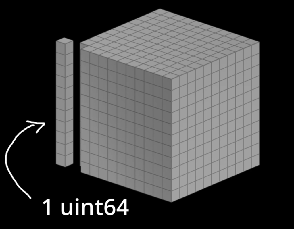
Each of these uint64 is representing a full ‘pillar’ of blocks in the chunk, as shown above. This does mean our chunk size is limited to 64 blocks (1 bit per block), which is fine in my case.
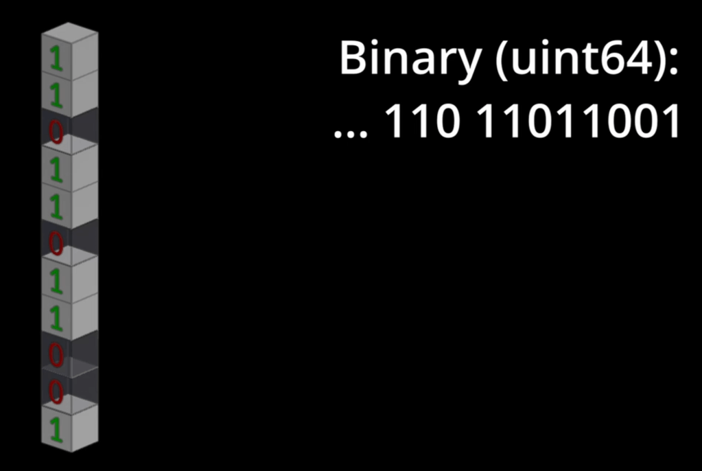
The above is just an extra illustration with some blocks as solid, some others as empty.
This presence mask will be very useful for quickly finding which faces are visible (see below), but I think it’s important to also mention that this data can be used in all sorts of ways: collision detection is an obvious example, pathfinding, etc. So, even if you didn’t plan on having this extra data for your chunks, there are may benefits to it, not just for meshing!
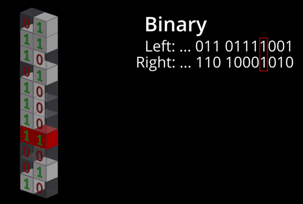
Now that we have our ‘pillars’ encoded as single integers, we can start comparing adjacent pillars together. Previously, we were looping through every single block one by one, checking 6 adjacent blocks to find out whether they’re empty or solid.
With this technique, we compare 64 blocks at a time! If you’re familiar with bitwise operations, you should have already guessed how we’re going to do it.
The previous image highlights the same bit from 2 adjacent pillars. The next one gives the final result we can reach with these informations:
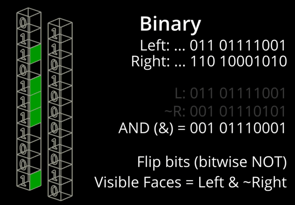
We can output another uint64 integer from those 2 pillars, by inverting the adjacent one (the one on the right in the above image) and applying a bitwise AND with the first pillar (the one we’re trying to define the visible faces for).
By doing this, we end up with a mask containing set bits (1) only on faces that are visible.
We just need to do this again for all other axis. The up and down check is even simpler : we’re comparing the pillar with itself, but with bit shifted up or down (<< and >> operators).
Greed is no longer a sin
Now that we know which faces need to be meshed, we can just… well mesh them. Put a quad there (2 triangles), then boom, you’re done.
On modern machines, unless you’re too greedy ambitious, this should be fine. Our machines, the GPUs especially, have become so good that even with relatively big maps, most systems would do a decent job here.
But what if I told you there was a way to generate a lighter mesh for your chunk, looking indistinguishable from the one you have now, AND that it will be even faster to compute? A miracle, right?
The presence mask mentioned in the previous step will help us again for this one.
For now, with what we’re going to call the naive meshing approach, a chunk mesh might look like this:
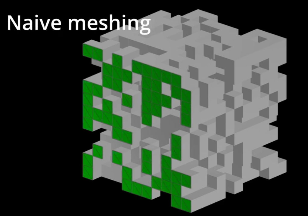
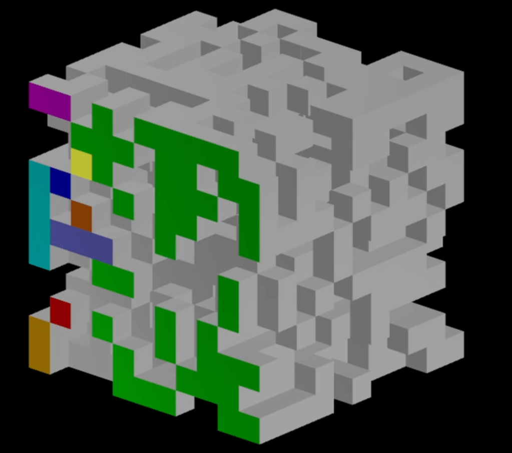
However, we could be more greedy and merge some of those faces together, resulting in this:
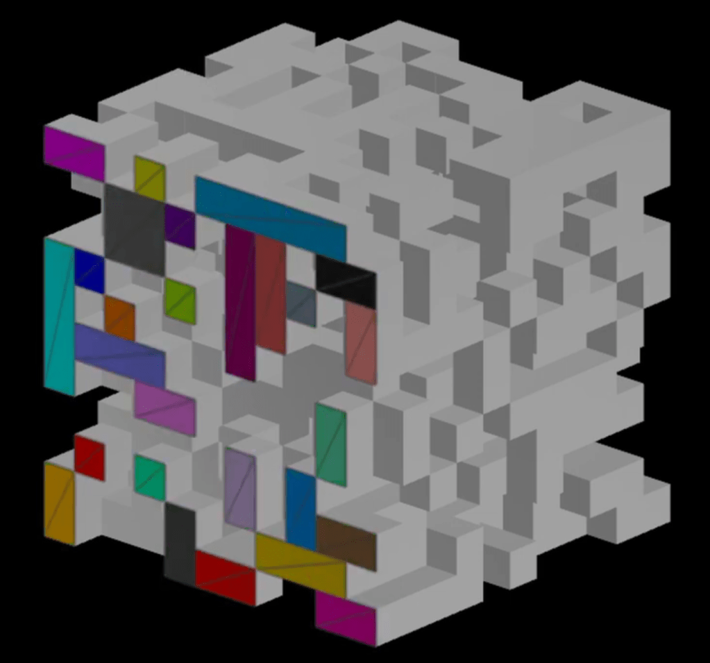
For the player, the result will be the same, but hopefully you can see by comparing the 2 previous images that the greedy meshing approach gives us a lighter mesh.
Instead of meshing faces one by one, we continue to check the next one in the same axis: if the next face is also visible and the block is of the same type, we just extend the current face (instead of creating a new one).
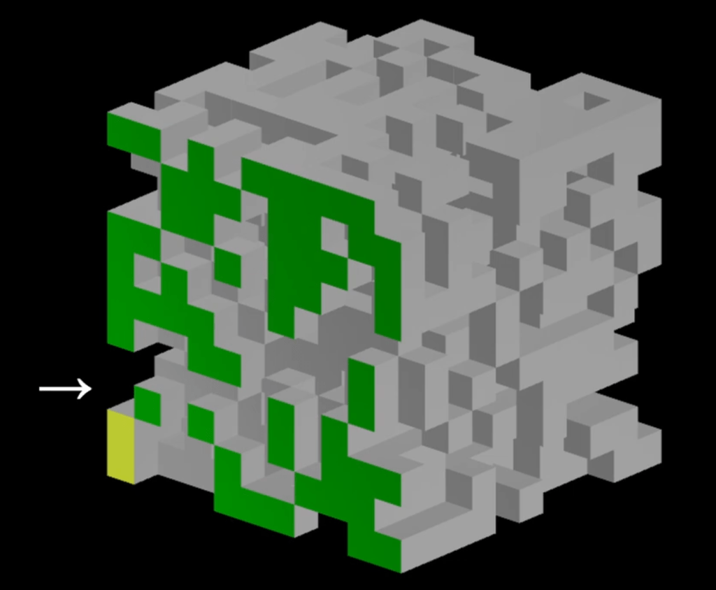
When we reach the end of the axis or, like shown above, if the next face is not visible, we can finally stop here and add the quad to the current mesh.
Each time, we can check in the other axis as well, to potentially extend the greedy face even more! The following series of images illustrates this:
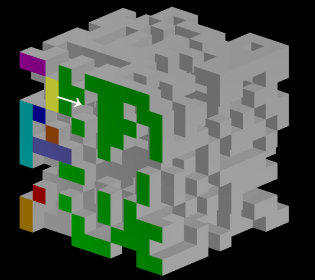
If you’re using the presence mask from the previous step, you can make this algorithm so fast that it will be even faster than meshing one face at a time. It’s a win-win: lighter meshes, faster!
Here is a public repository showing this algorithm: https://github.com/cgerikj/binary-greedy-meshing/tree/v2.0
It is very similar to what I’ve done for my project, but somehow faster than mine! (not sure why, I might take a look in the future, but the performances of my current algorithm is already faster than what I need!)
You can also check the video at the top of this article, it explains step by step the meshing process (without going into code / technical details).
A quick word about ambient occlusion
Before we wrap, an important aspect of the blocky game look is the ambient occlusion that is baked onto the vertices. This can drastically improve the look of your game, in my opinion, and is very easy to implement.
Again, some good articles have been written on the subject already, so I won’t repeat what’s already been demonstrated: https://0fps.net/2013/07/03/ambient-occlusion-for-minecraft-like-worlds/
I do go over it in the video (top of the article), so here is just the summary of the different configurations of ambient occlusions for a single vertex (highlighted in orange):
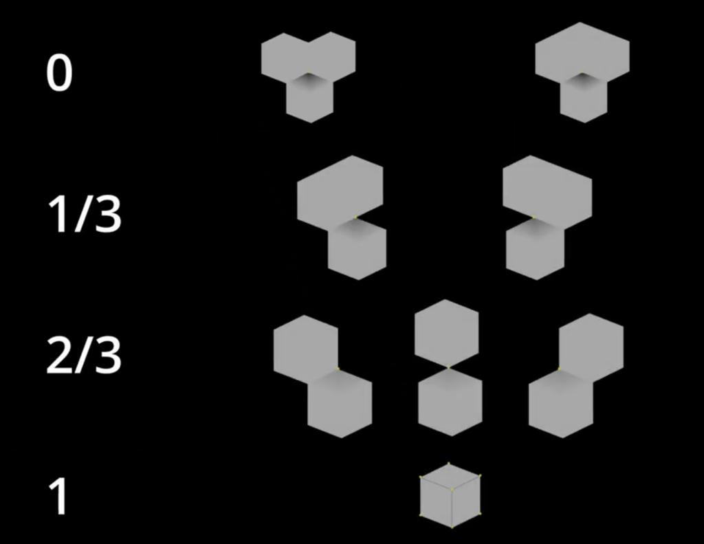
The gist of it is that, to compute the ambient occlusion fo a given vertex, we just need to compare the adjacency of the blocks (as shown above):
AO = SideA && SideB ? 0.0 : 1.0 – (SideA + SideB + Corner) / 3.0
Now, regarding greedy meshing: when trying to merge the current face with the next one, we only allow faces that have the same ambient occlusion configuration. That’s as simple as that.
Fixing the mesh in-between chunks
Lastly, there is an important aspect of meshing that we need to adress: so far we’ve only been caring about meshing the chunk itself, but our map is made of many contiguous chunks.
After implementing all of the above, especially if you use ambient occlusion, you will start noticing seams between chunks. Indeed, because each chunk is only aware of its own blocks, the mesh will not be an accurate representation of the contiguous space between chunks.
The ‘dumb’ way of fixing this is to arrange your code so each chunk can only be meshed when all its adjacent chunks have been generated. Then you need your meshing code to query adjacent chunks data, which might be getting queried or modified concurrently in another thread.
You guessed it: it’s code hell. It’s doable. You can do it. But it’s going to be a nightmare.
A much more simple solution, which might appear suboptimal, is to instead have the chunks generate and extra block in all directions. This generation should be made so these extra blocks at the chunk border are the same blocks as the adjacent chunk border blocks. If this soup of words is confusing, look at the following image:

This is very easy to implement, as it only requires you to use slightly different computations for defining a chunk location versus defining a chunk size.
I’m assuming you will be using pseudo-random methods to generate your blocks (meaning that the duplicate blocks shown in the above image will be consistently the same, whether they are generated in chunk A or chunk B, as long as their world location is the same).
Conclusion
As most of the other articles, I didn’t go into technical details and didn’t show actual code examples, as it is always very much project (and language) dependant. However I did link a couple of pages which will help you, should you want to implement the same system.
The main take-away is that you should only spend time on what is actually visible.
In the next article, I will be presenting even further optimisation regarding meshes: LODs (level of details) for the chunk meshes and, perhaps more interestingly, LOGs (level of genetarion)…

Leave a reply to Chunks Levels of Details – Kaiagan Cancel reply